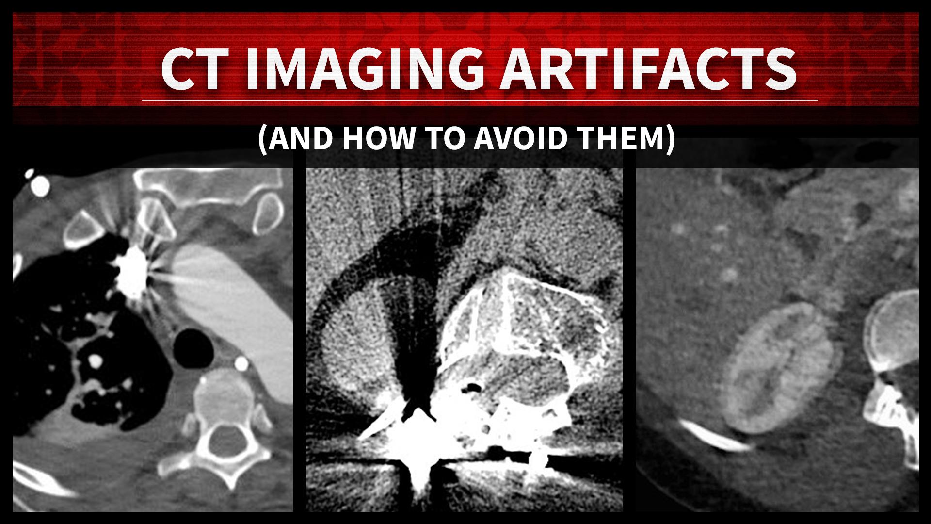
Computed Tomography (CT) imaging artifacts are unintended and undesirable patterns or distortions that can appear in CT images due to a variety of technical factors. It is important for medical professionals to recognize and mitigate these artifacts to ensure the highest quality and accuracy of CT images. These artifacts can obscure important anatomical details, alter tissue density values, and lead to misdiagnosis or misinterpretation by medical professionals. Radiologists, technologists, and medical personnel must remain vigilant in understanding the causes of artifacts and implementing techniques to reduce their occurrence, enabling precise diagnoses and optimal patient outcomes. Below are some of the most common types of artifacts, what causes them, and how to avoid their occurrence.
Patient-Based Artifacts
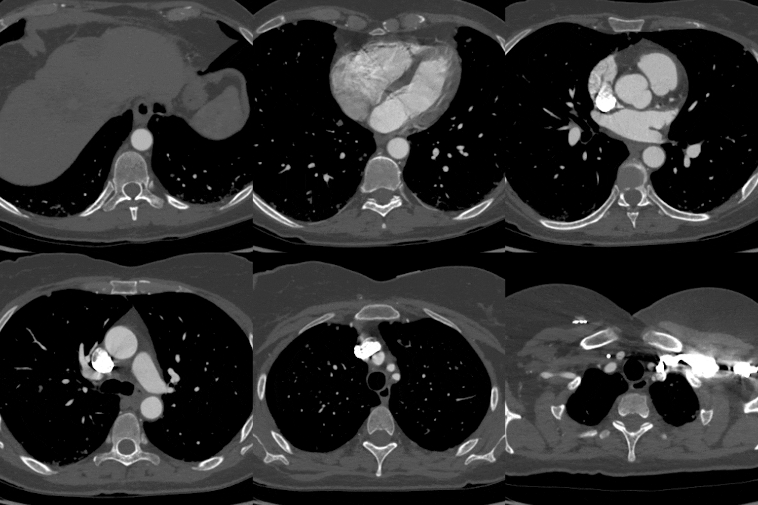
Contrast Media Artifacts
- Cause: Non-uniform distribution of contrast agents can lead to streaks and variations in tissue enhancement.
- Avoidance: Optimize contrast injection protocols to ensure even distribution. Consider using saline flushes to clear contrast from vessels.

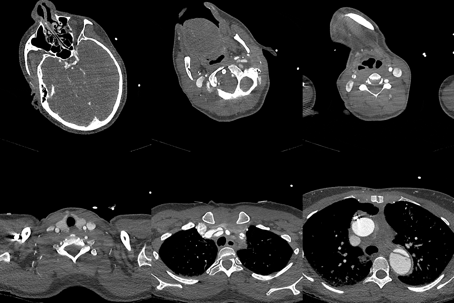
Motion Artifacts
- Cause: Patient movement during scanning disrupts the spatial alignment of the acquired data.
- Avoidance: Instruct patients to remain still during the scan. For uncooperative patients, consider using sedation or gating techniques. Faster scanning techniques can also reduce the likelihood of motion artifacts.
Physics-Based Artifacts
Beam Hardening Artifacts
- Cause: X-ray beam hardening results from preferential absorption of lower-energy X-rays by dense tissues.
- Avoidance: Use advanced reconstruction algorithms that correct for beam hardening. Adjust energy settings, and if possible, avoid high-density objects in the scanning area.
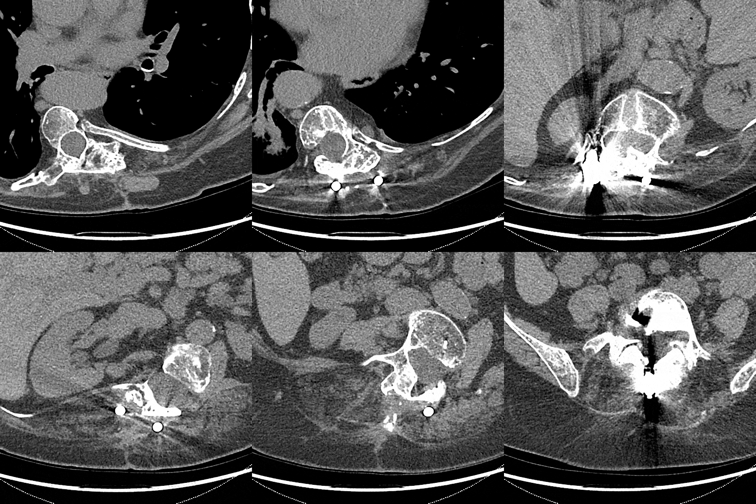
Metallic Artifacts
- Cause: Metal implants or objects absorb X-rays, leading to streaks and shading.
- Avoidance: Adjust scan parameters or use metal artifact reduction algorithms to mitigate artifacts. Use alternative imaging modalities (MRI, where appropriate) when metal is present.
Hardware-Based Artifacts

Ring Artifacts
- Cause: Malfunctioning detector elements or inconsistent sensitivity across the detector array.
- Avoidance: Regularly calibrate and maintain the CT scanner. Use post-processing techniques to correct ring artifacts.
Case courtesy of Henry Knipe, Radiopaedia.org, rID: 28033
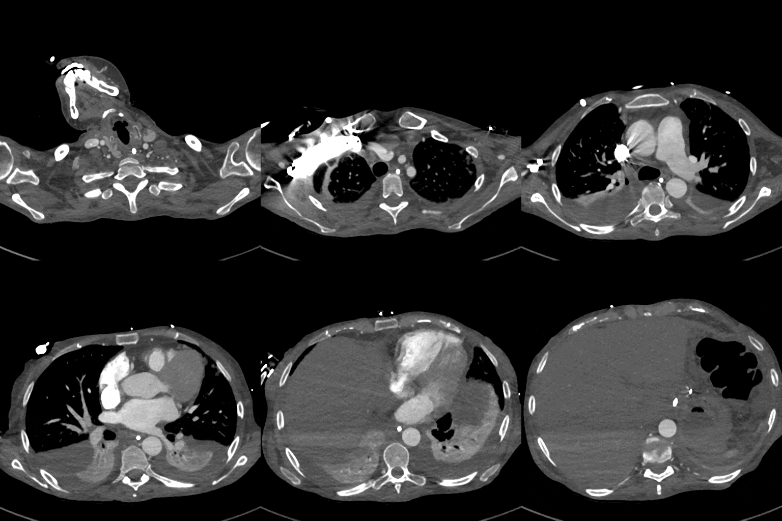
Scatter & Streak Artifacts
- Cause: Faulty detector elements or extreme attenuation by certain tissues.
- Avoidance: Use anti-scatter grids, collimators, or software-based scatter and streak correction algorithms. Employ appropriate beam collimation and collimators. Routine scanner maintenance and calibration are essential.
Optimal Image Series

Optimal Scan
The series of images above provides a visual representation of an artifact-free scan, which is considered optimal for processing and clinical interpretation.
3DQ Lab – Grant Building
3DQ Lab – Clark Building
Learn More About the Lab
Copyright © Stanford University

