

How is Stitching Performed?
The stitching process begins by capturing multiple scans with each scan slightly overlapping the region of the next. These scans are positioned and registered using specialized software, which ensures that the common features in the overlapping sections align. This accuracy is vital for the integrity of the final image. Following alignment, the software processes the images by identifying and merging similar points or features in the overlapping areas. The final step is a quality check to identify and fix any distortions. The final result is a detailed and accurate image of a much larger area than what a single scan could achieve.
Encountering “lines” on a stitched scan is normal and expected. These lines often appear at locations where individual scans are joined together, marking the boundaries of each original image. Additionally, variations in contrast can sometimes be noticeable at these locations. These features are inherent to the stitching process and do not typically impact the interpretive quality of the medical images.
Figure A (Right): Magnetic Resonance Imaging (MRI) has a tendency to distort the edges of a large scan. Some of this distortion remains even when stitched together, but can still prove useful for imaging.
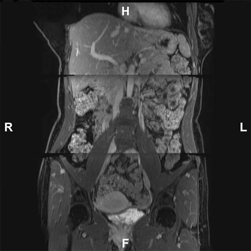
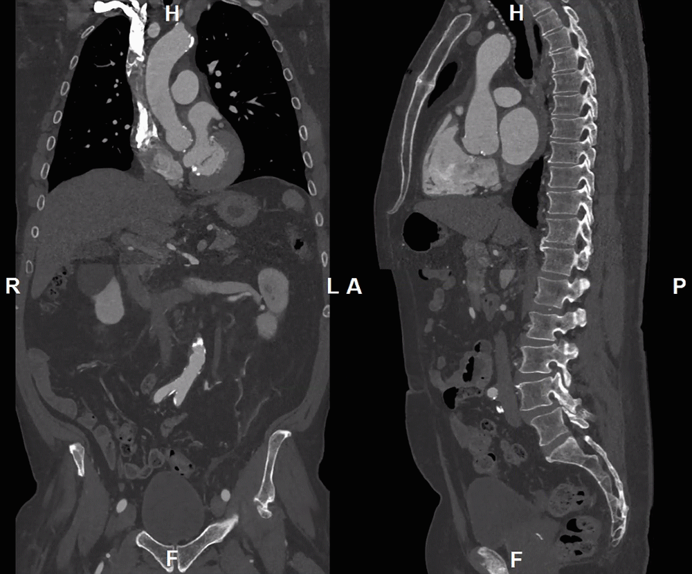
Figure B: An example of a poorly stitched scan. While the spine is correctly stitched, the soft tissue is misaligned and cannot be used for accurate diagnosis or measurements.
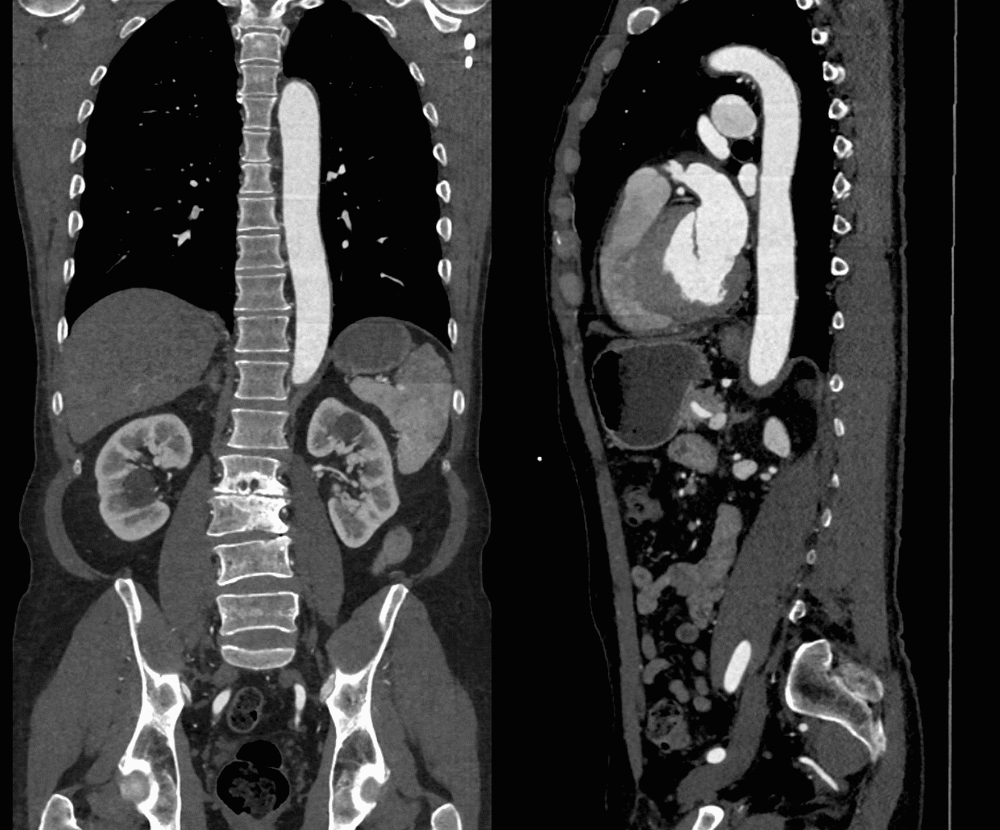
Figure C: A correctly stitched image. While some distortion is visible along the stitched edges (mostly contrast differences), it does not inhibit diagnosis or measurements.
Transcatheter Aortic Valve Replacement (TAVR)
Cardiothoracic Surgery (CVS)
MR Venogram

Figure D: Various TAVR measurements showing diameters, angles, and Curved Planar Reformations (CPRs, learn more here)
The TAVR program uses stitching to merge images of the chest and abdomen. The stitched imaging is used for evaluating patients with heart failure who may be suitable for the TAVR procedure, a less invasive method of implanting a new heart valve using a catheter. The stitched imaging provide an extensive view of the iliac arteries, stretching from the groin to the aortic valve. Learn more about TAVR here.

Figure E: Various CVS measurements showing diameters and their measured locations along the descending aorta.
The CVS program uses stitching to create a comprehensive view of the descending aorta. From these images diameters of the aorta are created at standardized locations and tracked via a graph for changes over time. When these measurements reach a specific threshold the patient is admitted for surgical intervention to avoid rupture.

Figure F: Venogram Maximum Intensity Projections (MIP) are used to display the abdominal, pelvic, and lower extremity blood vessels for vascular diseases.
Magnetic Resonance Venography (MR Venography) is an imaging technique that provides detailed views of abdominal, pelvic, and lower extremity veins by stitching together chest and abdominal scans. This is used for detecting vein narrowing (stenosis), assess post-thrombotic changes, and evaluate varicose veins.

