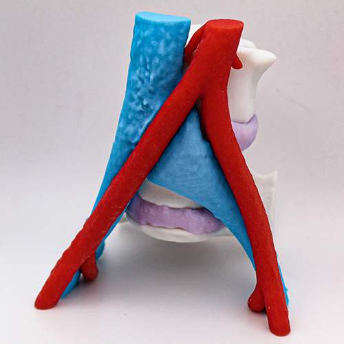
In a recent case at the 3DQ Lab, we were presented with a patient exhibiting symptoms of May Thurner Syndrome (MTS). This patient was experiencing swelling, pain, and discoloration in the left leg, which are classic signs of this condition. MTS is an uncommon vascular condition where the left iliac vein is compressed between the right iliac artery and the spine. This condition can lead to deep vein thrombosis, a serious condition where blood clots form in the veins. To gain deeper understanding of the patient’s condition a 3D Print was requested.
Figure A (Right): The left iliac vein (blue) is being compressed by the right iliac artery (red). The bone of the vertebrae and pelvis (white) and intervertebral discs (purple) were included for context.
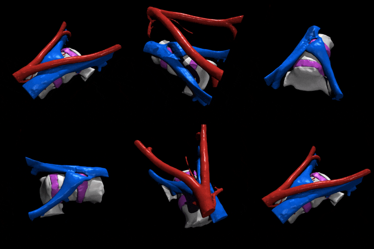
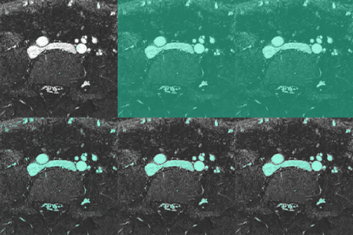
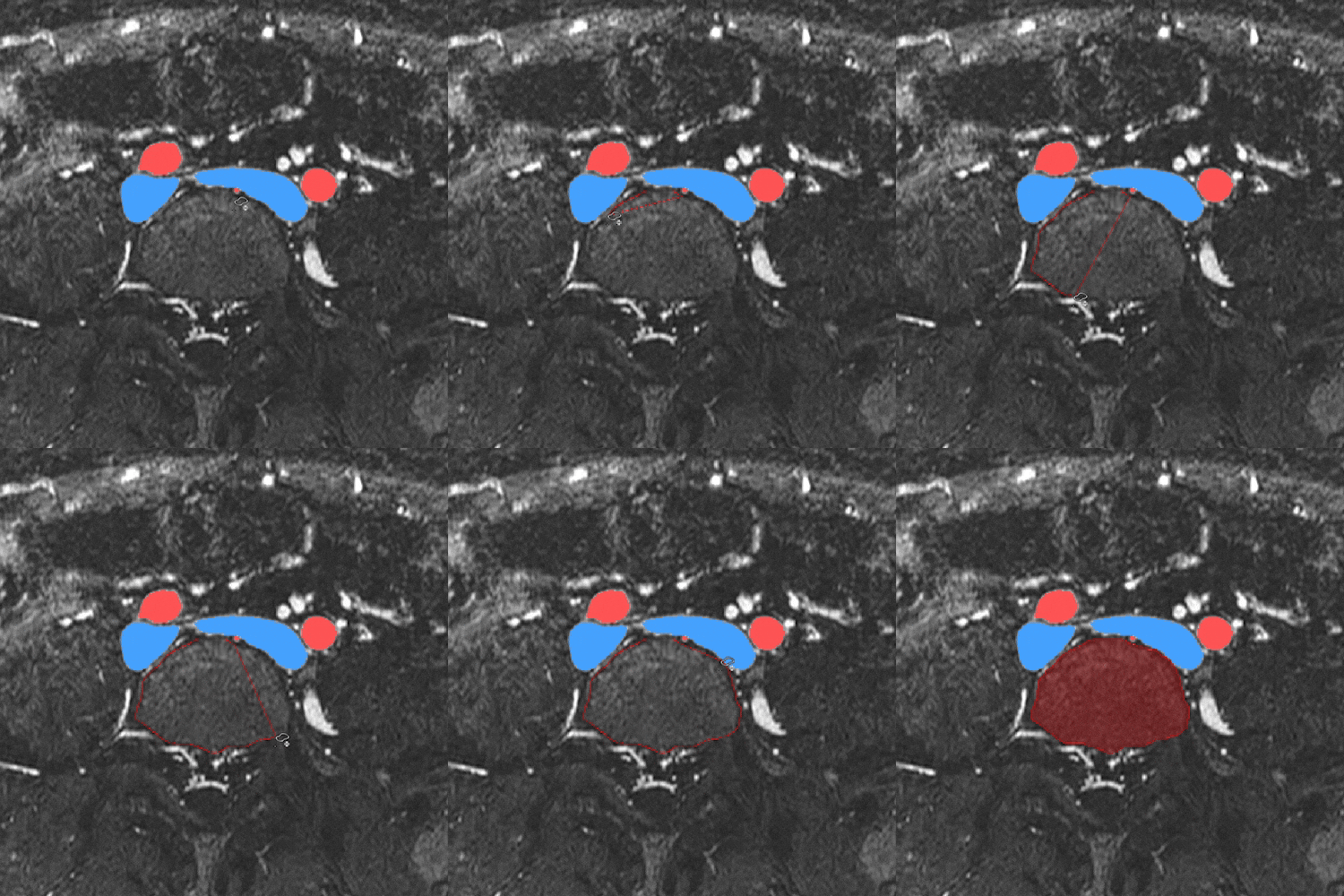
We started the 3D modeling process by dividing the left iliac vein, right iliac artery, spine, and intervertebral discs into separate, distinct models. For easy identification, each anatomical part was color-coded. We used thresholding and window leveling techniques to make sure these models matched the patient’s actual anatomy as closely as possible. Some manual editing was performed to sharpen the details and refine the edges, particularly around the region of iliac vein compression. This process was done using FDA-cleared software. Learn more about segmentation here.
Figure B (Left): Applying a threshold to isolate the iliac veins and iliac arteries.
Figure C (Right): Manual segmentation of the vertebrae and intervertebral discs.
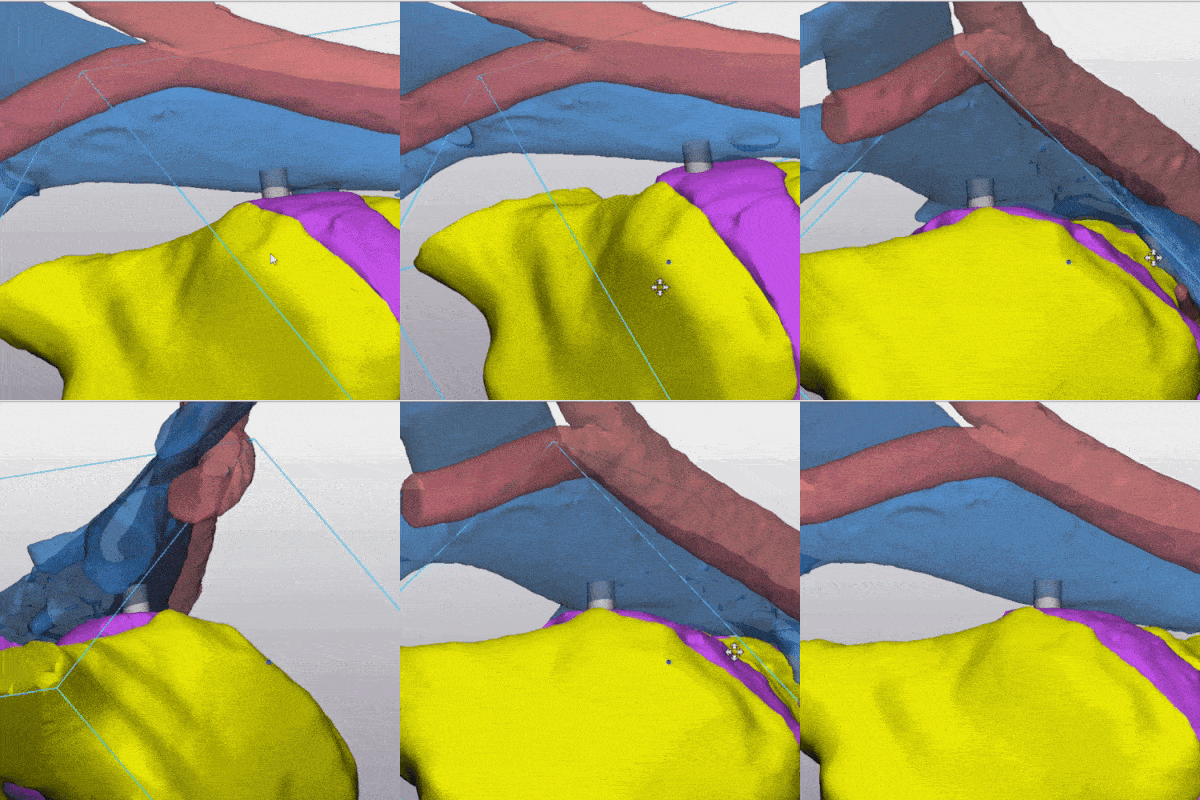
The segmented images were converted into 3D mesh models and then imported into a 3D editing software. To create neat and even edges, we trimmed the top and bottom of the models. Pegs were inserted at specific points between the anatomical structures to ensure stability and accurately maintain their relative positions, especially in areas where the anatomy is not in direct contact. Some areas of the mesh were refined and smoothed to guarantee that the 3D printing process would be free of errors. This step was crucial to ensure that the final 3D print would be of high quality and accurate to the patient’s anatomy. Learn more about exporting STL files for 3D printing here.
Figure D (Left): Trimming the 3D mesh to create tidy, uniform edges.
Figure E (Right): Pegs added to secure the model in anatomical position.

The 3D model was printed using polyjet technology, a printing method that layers different materials in fine jets, allowing for combinations of multiple colors and materials. We utilized five distinct colors to enhance clarity. Post-printing, the model was carefuly cleaned using a waterjet and specialized support removal tools. It was then left to dry for several hours, ensuring it was fully prepped and ready for delivery to the requesting radiologist.
Figure F (Right): Photograph of the completed 3D print.